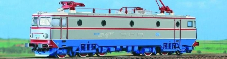
This page contains pictures of a Siemens ER20 Hercules locomotive from WLB (Wiener Lokalbahnen – an Austrian transportation company). The Locomotive model is at HO scale and manufactured by the German company Piko.
You can find the manual that came with it by clicking on this link.
The manual includes detailed schematics.
Below, you have a first photo gallery of this locomotive:


I didn’t like that the locomotive didn’t have rear red lights, so I modified it. This locomotive is a rather cheap one, so I experimented on it. Don’t try do this with an expensive locomotive (but then, of course, expensive locomotives already come with white and red bidirectional lights).
Let’s continue with the modifications I made to it.
The first question that first came to my mind was how to make the red back lights turn on with the white lights in the front and how to make them turn off when the locomotive moves the other way. Fortunately, the logic already existed, because the locomotive already had white frontal lights that were turned on and off depending on the sense of the movement. So all I had to do was to connect the wires for the red lights with the wires for the white lights at the opposite side.
Now, initially the locomotive had light bulbs that can light up when powered between let’s say 1.5 Volts and 12 or 16 Volts, but LEDs have a rather fixed input voltage, and they require a regulator so that they don’t burn out. This is where the Zener diode comes into place. Let’s look at the scheme below (click to enlarge):

As you can see, the scheme is symmetric. When “Vin” from above is positive and “Vin” from below is ground, the right half of the scheme is activated and turns on the front lights and the rear lights at the other head. When the polarity is changed, the left side of the scheme is activated and the corresponding front and rear lights are turned on, while the other are off. I took the liberty to power the circuit directly from the input power (from the tracks), because I didn’t want to modify the existing circuit except the light bulbs that I removed. I connected my circuit in parallel with the existing one. Besides, I didn’t need the semiconductor diodes used for the light bulbs, because LEDs are themselves diodes and only light up when connected in one way.
The list of the used pieces is the following:
2 Zener diodes at 3.0 Volts, 0.5W
2 Resistors of 1K Ohm
2 Resistors of 300 Ohms
6 white LEDs, 3mm, at 3.2-3.4 Volts
4 red LEDs, 3mm, at 2.4 Volts (I think);
one capacitor (non-electrolytic) of at least 7uF
The Zener diodes are used as voltage regulators, so that the LEDs don’t burn out.
The 1KOhm resistors are needed for the Zener diodes (the rest of power has to go somewhere, and that’s the role of these resistors)
The resistors of 300 Ohms were needed for the red LEDs, because the Zener diodes offer them a higher voltage (3Volts) than the red LEDs need. Also, the red lights shouldn’t light too powerful, so I would have used these resistors anyway.
After I finished the circuit and tested it on the locomotive, I realized that from time to time, when the locomotive was passing with high speed over the rail joints, the WHITE LEDs at the rear would sometimes flash shortly. So I added the capacitor to solve this problem. I didn’t have just one, so I added 7 capacitors, each having around 1uF capacity, and connected in parallel. The 7uF capacity was determined experimentally.
In this case, I used 3mm LEDs, because I thought there was enough space for them, but I had to polish them, so they could fit. Next time, I will use SMD LEDs.
Oh, and next time I’ll read the specifications of the locomotive more carefully. It’s embarrassing, but… after I modified it, I realized that the model was actually a 16V AC one. I was under the impression that it was a 12V DC (at least that’s what I thought that ordered from the shop). It works fine in direct current (I think the diodes inside of it convert the AC to DC anyway – half wave rectification, probably – but that’s just an assumption, I haven’t investigated the electrical part too much, because my electrical circuit is connected in parallel with the rest, so I didn’t care too much about it) and the lights may work just fine in alternative current (if you’re all right with lights that pulsate at 50 Hz… hardly noticeable; Oh… the 1KOhm resistors may overheat at 16V – my scheme was designed for a maximum 12V input voltage).
Here you have pictures of how it looks after I modified it:


I found on the internet some pages about ER 20 that you may find useful:
At this link you have more pictures of the dismantled locomotive, including the transmission. I think it’s the DC version (the electrical circuit looks different).
Here you see a comparison between the Piko version and the Kuehn version of the ER20 locomotive. They seem to be TT models and the Kuehn one comes with reverse lights.
